
Page 97 - Demo
P. 97
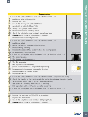
95GENERAL PURPOSE DRILLINGTroubleshootingDeviation of Hole Tolerance1 Check the runout and make sure it is within 0.02 mm T.I.R.(radial and axial cutting points).2 Reduce feed rate.3 Check the chisel point runout and make sure that it is within 0.02 mm T.I.R.4 Wrong cutting edge. replace head.5 Increase workpiece chucking force.6 Check the adaptation. use hydraulic clamping chuck, MAXIN power chuck or side clamping systems.7 Increase internal coolant pressure.%u00d8 > D nominal + 0.15mm%u00d8 < D nominal - 0.03mmD nominalSurface Finish Too Rough1 Check the runout and make sure it is within 0.02 mm T.I.R. (radial and axial).2 Adjust the feed for improved chip formation.3 In case of chip jamming - Increase the coolant flow and/or reduce the cutting speed.4 Increase the coolant pressure.5 Check the chisel point runout and make sure it is within 0.02 mm T.I.R.6 Use pecking cycle.7 Use double margin geometry.RaHole Not Straight:1 Use 2M geometry.2 Drill a pre-hole for centering (check recommendations for pre-hole operation).3 Increase coolant pressure, improve jet direction in case of external coolant supply.4 Increase the feed.Inaccurate Hole Position1 Check the runout and make sure it is within 0.02 mm T.I.R. (radial and axial).2 Check the stability of the machine spindle, tool and workpiece clamping rigidity.3 When drilling rough, hard or sloped surfaces (up to 7%u00b0), reduce the feed rate by 30%-50% when entering.4 Drill a pre-hole with a 140%u00b0 point angle for centering.5 Check the chisel point runout and make sure it is within 0.02 mm T.I.R.Burrs on Exit1 Reduce the feed rate by 30%-50% when exiting.2 Replace the worn head.3 Check the adaptation. use hydraulic clamping chuck, MAXIN power chuck or side clamping systems.
